Material Cards
Testing
Supported Models
Development Workflow
Model Selection
Deliverables
FAQs
Enquiries
Simulation Analysis Lab
Material Cards

1.1 What is a material card?

A material card is a set of material model parameters obtained by translating experimentally measured material behaviour through data processing and calibration into a form that a finite element solver can use. Depending on the model, it can describe elasticity and plasticity, strain-rate and temperature effects, anisotropy, damage and fracture, foam crushing, adhesive failure, and multiple damage modes in composites.

Material cards connect experimental material properties with CAE finite element simulation.

1.2 How do a material model, a material card and a K file differ?

Term Definition Role
Material model A mathematical description of material response under loading, such as MAT24, MAT187 or MAT169. Defines which model is used to describe the material.
Material card The parameters calibrated from test data for a specific material. Defines the values to use for that material within the chosen model.
K file / keyword file An input file used in keyword-based solver systems such as LS-DYNA to define a finite element model. The material card is typically only one part of the complete input file.

For example, MAT187 is a material model. Calibrating a specific grade of PA66-GF produces a MAT187 material card for that material. A complete finite element input file additionally requires nodes, elements, PART and SECTION definitions, contacts, loads, boundary conditions and control parameters.

Further reading — A material card is part of a workflow linking testing, parameter identification and the finite element model. High-speed automotive loading also requires consideration of strain rate, failure and different stress states. See Material Cards for High-Speed Automotive Crash Simulation and Their Application for related material data requirements.


Testing

There is no fixed test package suitable for every material and loading condition. The test matrix depends on the material type, simulation scenario, target model, strain-rate range, temperature range and whether failure must be represented.

2.1 Common tests for polymer material cards

Test Common standards / reference methods Main parameters or data Typical application
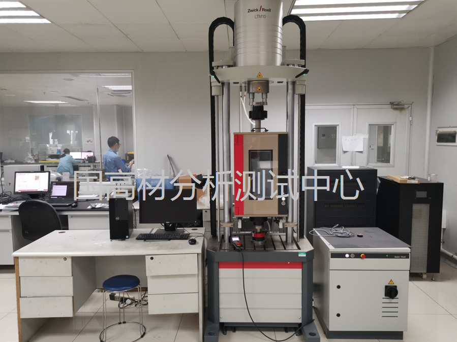
Quasi-static tensile testing of plastics ISO 527-1, ISO 527-2; ASTM D638 Elastic modulus, yield response, stress–strain curves and strain at break; transverse strain measurements can provide Poisson’s ratio. Basic inputs for MAT24, MAT187 and similar models.
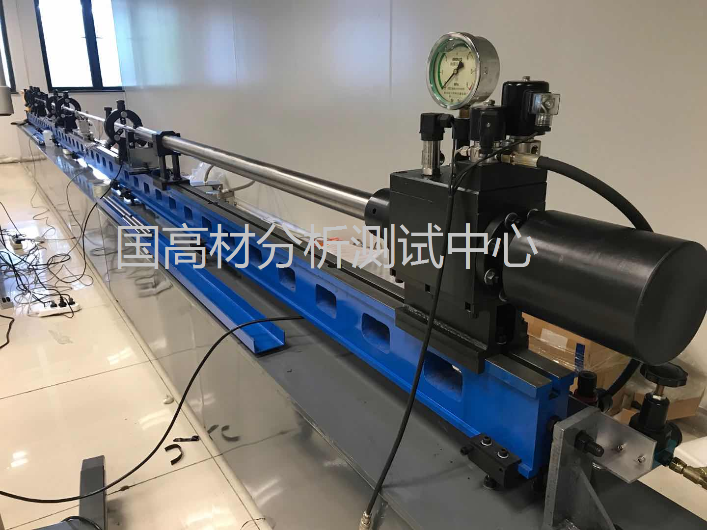
High strain-rate tensile testing ISO 18872, together with appropriate high-speed tensile test methods Stress–strain curves at different strain rates; rate dependence of yield and hardening. Crash, impact and drop simulation.
Compression testing of plastics ISO 604; ASTM D695 Compressive modulus, yield response and stress–strain behaviour. MAT187 and models addressing foam or tension–compression asymmetry, subject to material applicability.
Flexural testing of plastics ISO 178; ASTM D790 Flexural modulus, strength and structural response. Model validation and structural response evaluation.
Instrumented puncture testing ISO 6603-2 Impact force–displacement response, energy absorption and failure behaviour. Validation of impact and failure models.
Charpy impact testing ISO 179-1; ASTM D6110 Impact strength and brittle/ductile behaviour. Material screening and supplementary failure assessment.
Tensile-impact testing ISO 8256 Tensile-impact response at elevated loading rates. Supplementary dynamic response assessment.
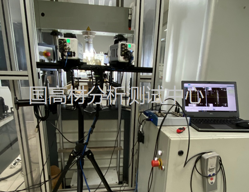
Digital image correlation (DIC) Conducted alongside the relevant tensile, compression or shear test Full-field strain, local strain concentrations, necking and actual deformation. Inverse identification of constitutive and failure parameters.
Temperature-dependent mechanical testing Relevant methods such as ISO 527 and ISO 604, with an environmental chamber Elastic, yield, hardening and failure data at different temperatures. Low-temperature crash and high-temperature structural simulation.

2.2 Common tests for fibre-reinforced composites

Test Common standards / reference methods Main parameters or data
Composite tensile testing ISO 527-4 / ISO 527-5; ASTM D3039 Directional elastic moduli, strength, Poisson’s ratios and failure strains.
Composite compression testing ASTM D3410; ASTM D6641 Compressive modulus, strength and failure modes.
In-plane shear testing ISO 14129; ASTM D3518 In-plane shear modulus and strength.
V-notched shear testing ASTM D5379 / ASTM D7078 Shear stress–strain response and strength.
Composite flexural testing ASTM D7264 Flexural modulus and strength.
Dynamic impact testing Drop-weight or other dynamic loading tests selected for the material and structure Impact energy absorption, damage evolution and dynamic failure.

Unlike conventional unreinforced plastics, composite material cards also need to account for material directions, lay-up, fibre and matrix damage, and anisotropy.


Supported Models

Materials can exhibit very different mechanical behaviour. A single model should not be used indiscriminately for every material. Guogaocai Analysis and Testing Center can design material tests and calibrate parameters according to the material system, application and model requirements of the target solver.

3.1 MAT24 — Elastoplastic modelling for engineering crash analysis

MAT24 (*MAT_PIECEWISE_LINEAR_PLASTICITY) represents elastoplastic behaviour using piecewise stress–plastic strain curves and can include strain-rate effects. It is suitable for selected engineering plastics and applications prioritising engineering crash response, structural strength and efficient material model development.

  • Density

  • Elastic modulus

  • Poisson’s ratio

  • Stress–strain curves at different strain rates

  • Failure parameters where required

3.2 MAT187 — Detailed constitutive modelling of polymers

MAT187 (*MAT_SAMP-1) can represent complex nonlinear polymer behaviour, including tension–compression asymmetry, pressure-dependent yielding, multiple stress states, plastic volume change, strain-rate effects, damage and failure. Typical material systems include PP, PC, ABS, PC/ABS, PA and glass-fibre-reinforced engineering plastics.

  • Uniaxial tension

  • Uniaxial compression

  • Shear

  • Testing at multiple strain rates

  • DIC measurements

  • Failure tests under different stress states

  • Temperature-dependent tests where required

3.3 MAT169 — Structural adhesives and bonded joints

MAT169 (*MAT_ARUP_ADHESIVE) is one of the models used for adhesive joint behaviour. It can represent damage and failure of adhesive layers under tensile, shear and mixed-mode loading. Typical applications include automotive structural adhesives, battery-pack adhesive joints and connections between dissimilar materials.

  • Elastic modulus

  • Poisson’s ratio

  • Tensile strength

  • Shear strength

  • Mode I / tensile fracture energy

  • Mode II / shear fracture energy

  • Strain-rate-dependent data where required

3.4 MAT83 — Foam materials

MAT83 (*MAT_FU_CHANG_FOAM) represents the nonlinear compression, crushing and unloading behaviour of foams. Typical applications include EPP, EPS and PU foams, automotive seating foam, energy absorbers and protective packaging.

  • Density

  • Compressive stress–strain curves

  • Crushing behaviour at different strain rates

  • Unloading and recovery behaviour

3.5 MAT55 — Damage modelling of fibre-reinforced composites

LS-DYNA groups MAT54 and MAT55 under *MAT_ENHANCED_COMPOSITE_DAMAGE. The Center can test and calibrate parameters for MAT55 and other composite models according to the material system, lay-up and simulation objectives.

  • Directional elastic moduli

  • Poisson’s ratios

  • Shear moduli

  • Tensile strength

  • Compressive strength

  • Shear strength

  • Parameters for the relevant failure modes

3.6 GISSMO — Damage and failure for crash simulation

Where crash or impact simulation must predict crack initiation and progressive failure, GISSMO damage and failure parameters can be developed. Tests under different stress states are typically needed to establish relationships between fracture strain, stress triaxiality and other relevant variables.

  • Unnotched tensile tests

  • Tensile tests with different notch geometries

  • Shear tests

  • Punch tests

  • Dynamic failure tests where required


Development Workflow

A material card is not created by simply copying an experimental curve into software. Development follows an integrated testing, data processing, modelling and validation workflow.

Step Material card development workflow
1 Confirm the material and application requirements
2 Select the target material model
3 Design the test matrix
4 Perform quasi-static, dynamic and multiaxial tests
5 Process DIC measurements and experimental data
6 Convert engineering stress–strain data to true material response data
7 Identify constitutive parameters through fitting and inverse analysis
8 Generate the material card
9 Validate the simulation at element or structural level
10 Deliver the material card and technical report


Model Selection

Selecting Models for Different Materials and Applications

Material / application Key behaviour Models to consider
Conventional engineering plastics Elastoplasticity and strain-rate dependence MAT24
Polymer components for crash applications Tension–compression asymmetry, multiple stress states and rate dependence MAT187
Automotive structural adhesives and bonded joints Tensile, shear and mixed-mode failure MAT169 and other adhesive models
EPP / EPS / PU foams Crushing, energy absorption, unloading and recovery MAT83 and other foam models
Glass- or carbon-fibre composites Anisotropy and multiple damage modes MAT55 and other composite models
Failure of plastics in crash loading Stress-triaxiality-dependent fracture and damage evolution GISSMO and other failure models

A more complex model is not automatically a better choice. Model selection and the test matrix should reflect material behaviour, the engineering question, available test data, required accuracy and the project schedule.


Deliverables
  • Raw test data

  • Stress–strain curves at different strain rates

  • DIC full-field strain data

  • True stress–true strain and plastic response data

  • Constitutive model parameters

  • Damage and failure parameters

  • Parameter results suited to the target solver and material model

  • Material model parameter files or data in the format specified by the client

  • Parameter calibration results

  • Simulation validation results

  • Material card technical report

A material card is not the same as a complete K file. If the project covers material parameter calibration only, the deliverables normally consist of the material model definition and calibrated parameters. If the project also includes development of a complete finite element model, delivery of a complete solver input file must be agreed in the project scope and contract.


FAQs

7.1 Is a material card the same as a K file?

No. A material card defines the constitutive and failure parameters of a material and is one component of a complete finite element input file. A K file can additionally contain the mesh, PART and SECTION definitions, contacts, loads, boundary conditions and control parameters.

7.2 Can a supplier’s tensile data be used directly for crash simulation?

Supplier data are not normally equivalent to a calibrated material card ready for engineering use. They often come from quasi-static standard tests, whereas crash analysis involves high strain rates, large deformation, multiaxial stress states and failure. Additional dynamic, multiaxial or failure tests, followed by data processing and calibration, are usually required.

7.3 How should MAT24 and MAT187 be selected?

MAT24 is suitable for relatively simplified elastoplastic and rate-dependent modelling. MAT187 is better suited to tension–compression asymmetry, pressure-dependent yielding and complex polymer behaviour. The choice depends on the material, simulation objectives and accuracy requirements.

7.4 Can material cards be developed for structural adhesives?

Yes. Their tests and models differ from those for conventional engineering plastics. Tensile, shear, fracture-energy and dynamic data can be used to develop parameters for MAT169 and other adhesive joint models.

7.5 Can foam materials be modelled for crash applications?

Yes. Foam modelling focuses on compressive crushing, energy absorption, strain-rate effects, unloading and recovery. MAT83 or another appropriate foam model can be selected for the application.

7.6 Can material cards be developed for composites?

Yes. Composite modelling must account for anisotropy, fibre direction, lay-up and different damage modes. Tensile, compression, shear and impact data can support calibration of MAT55 (*MAT_ENHANCED_COMPOSITE_DAMAGE) and other suitable composite models.

7.7 Why is high strain-rate testing needed for polymer crash simulation?

Loading rates in crash and impact events are typically much higher than in conventional quasi-static tensile tests. For rate-sensitive materials, using quasi-static data alone can bias predictions of yield, energy absorption, deformation and failure.

7.8 Can the Center supply a complete K file?

Material cards and complete K files are different deliverables. Depending on the project scope, the Center can provide material model parameters, material cards and calibration data. A complete finite element model file requires a separately defined project task and contractual scope.


Enquiries

For automotive crash analysis, EV battery-pack structural safety, consumer-electronics drop analysis, impact of engineering plastics, foam energy absorption, adhesive joints or glass- and carbon-fibre composite impact, Guogaocai Analysis and Testing Center can design a test matrix based on the material, loading conditions, target solver and material model.

Services cover material testing, data processing, constitutive parameter identification, material card generation and simulation validation. Model requirements supported include MAT24, MAT187, MAT169, MAT83, MAT55 and GISSMO.

Related service cases and technical articles


ONLINE MESSAGE
ONLINE MESSAGE
Please enter your contact information and we will reply to you as soon as possible.